Digging the FinEst Link: one of the most challenging tunnel projects on Earth
In this fourth news feed about the over 100 km long subsea tunnel project between Helsinki and Tallinn, we take a closer look at different aspects related to the design and the construction.
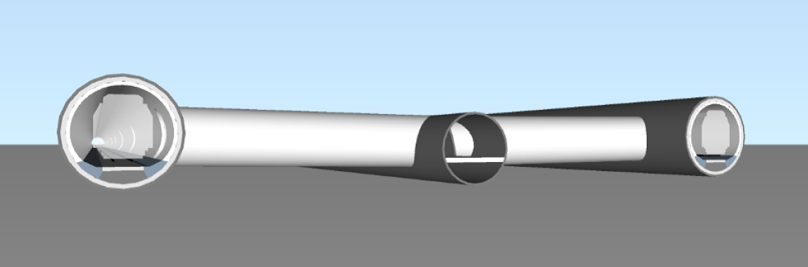
Figure: Tunnel layout for Finest Link – typical cross section
As discussed in our second news feed, a transversal tunnel scheme consisting of two single-track tunnels and one service tunnel with cross passages was assessed as the most suitable and best-possible tunnel solution for FinEst Link.
The design of the train tunnels is based on a clearance profile for the European standard 1435 mm railway-gauge (according to TSI UIC GC standard). Thus, the two single-track tubes have an excavation diameter of 10 m. The diameter of the central service tunnel (8 m) provides enough space for technical and safety installations and allows for the crossing of two maintenance vehicles.
The service tunnel will be excavated in advance and thus can be used as an exploratory gallery for the main tunnel drives. During operation, it will play an important part both for the maintenance and the safety concept of the tunnel.
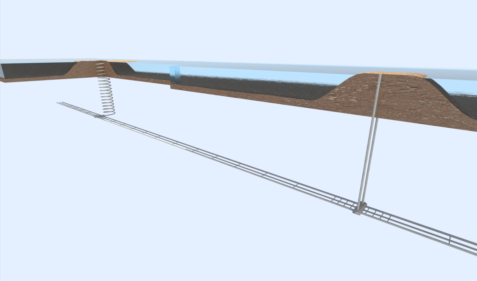
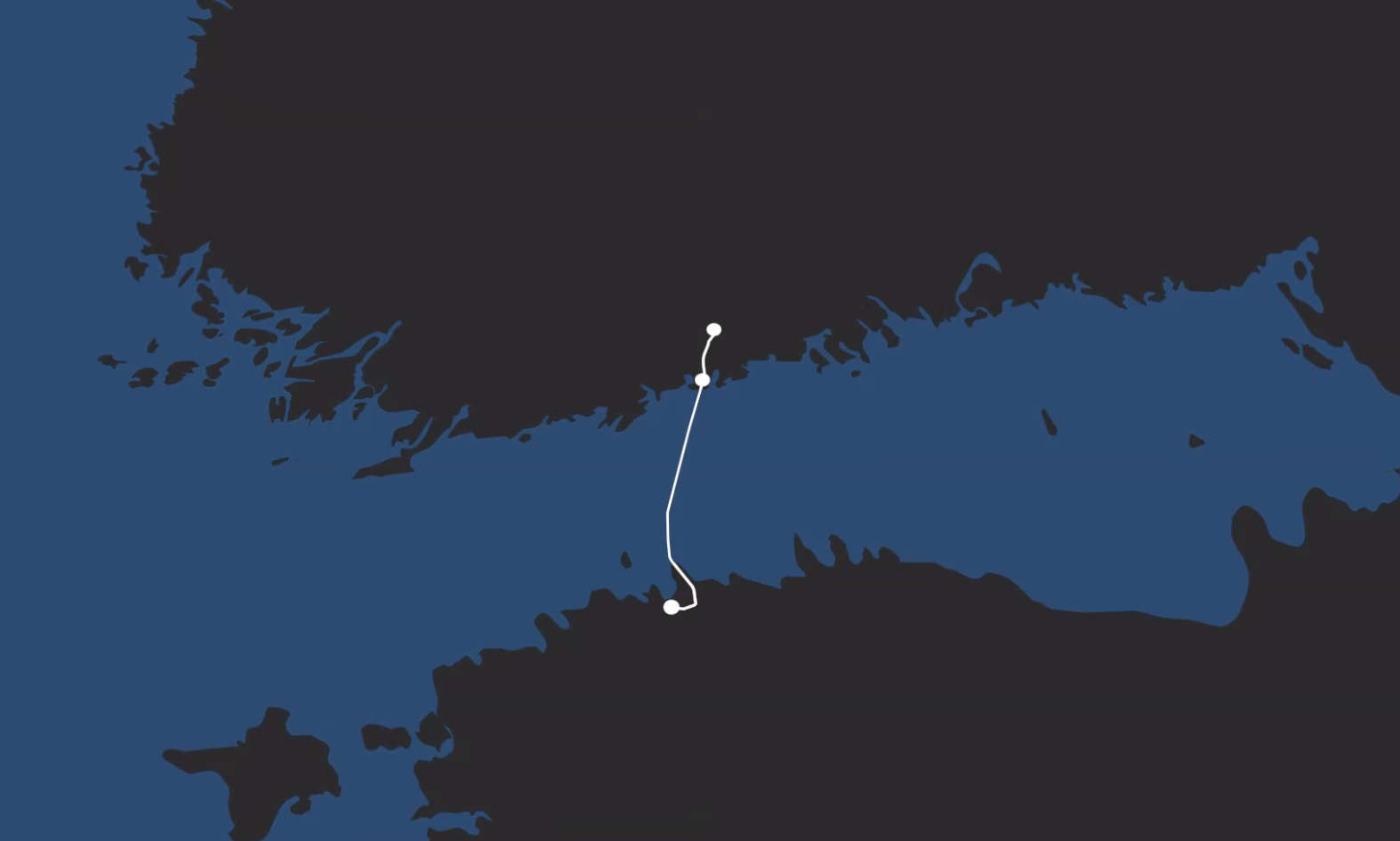
Figure: Finest tunnel system and intermediate accesses from artificial islands.
Intermediate attack points from artificial islands
To reduce significantly the construction time of long tunnels, it is indispensable to plan intermediate attack points from which multiple tunnel drives can start simultaneously. In addition, the provision of intermediate access points is beneficial for logistics, operations and risk mitigation.
For subsea tunnels, possibilities for providing intermediate accesses are technically demanding. Intermediate accesses have to be located in not too deep water and preferably at locations which split the entire tunnel in portions of fairly similar lengths. One solution is the installation of vertical shafts with a platform on top as is a common practice in the oil and gas industry. Another option is the creation of artificial islands, from which vertical access shafts or inclined access tunnels are built down to the tunnel level. For the FinEst Link the second option was chosen, since artificial islands offer several advantages compared to platform solutions.
For the FinEst Link, two artificial islands of approx. 400 m x 300 m will be created. They will be located in water depths of approx. 15 m and 20 m and will be built of material coming from the Finnish onshore tunnel excavation. Moreover, these islands will provide space for handling and storing the excavated material, for the installation of silos, batching plants, workshops and offices and for the construction of a harbor necessary for the logistics.
Two different access types from the artificial islands
Due to different geological conditions, two different sorts of access types will be constructed: on the Tallinnamadal island off the Estonian coast, two vertical shafts will be sunk to a depth of approximately 215 m below sea level. On Uppoluoto island, near the Finnish coast, the engineers are planning an inclined access tunnel of about 1’500 m length with a maximum gradient of 10%. As the dimensions of the artificial island are limited, it is planned to build a helix-shaped access tunnel.
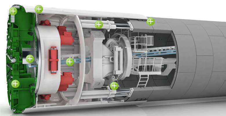
Picture: Example of a single shield TBM with segmental lining that could be used for the FinEst Link (source: www.herrenknecht.com)
Tunnel construction by means of Tunnel Boring Machines (TBM)
Construction time is a key parameter in tunneling. For long tunnels it is common practice to use Tunnel Boring Machines (TBM) as they offer two to three times higher advance rates compared to the drill-and-blast excavation technique.
As discussed in our third news feed, the FinEst Link will be mainly situated in competent and stable crystalline bedrock. These tunnel sections will be constructed either with single shield TBM or double shield TBM. In the Ediacara sandstone and the blue clay formations in Estonia, an active face support in the TBM will be required. In that type of rock, either a Mixshield or EPB Shield TBM will be deployed for tunnel construction. For the excavation of cross passages, rescue stations and intermediate accesses, the drill-and-blast technique will be used.
The tunnel will be lined with single-shell, pre-cast concrete segmental rings designed to bear the rock and water pressure. The segments will be sealed with gaskets to ensure the water tightness of the lining even for water pressure exceeding 20 bar, which is technically demanding. However, there are several references of TBM drives under similar high-water pressure.
Six simultaneous construction sections
Due to the intermediate access points, the FinEst Link will be divided into six construction sections (tunnel drives) that will be constructed in parallel. Since the excavation material from the Finnish onshore tunnel segment drilled in crystalline bedrock will be used for building the artificial islands, this section needs to be built first. The entire construction time – including the installation of the railway equipment as well as testing and commissioning – is estimated to last approximately 15 years. No buffer time is included in this calculation, yet some areas with reduced advance were considered.
Amberg Group: contributing to a smart use of space
The growing urbanization of the world is calling for a smart use of space. Combining competencies in the areas of civil engineering, surveying solutions and logistics, the Amberg Group is taking a leading role in designing tomorrow's Smart Cities and cutting-edge infrastructures, both underground and aboveground. Visit www.amberggroup.com and follow us on our social media channels: LinkedIn, Facebook and Twitter.
Related News